Flux Reference Manual

  • Welcome to Flux
  • Introduction
    • Installing the Software
    • The User Interface
    • Part Workflow
    • The Machine Database
  • Cut
    • Basic Workflows
      • Part Workflow
        • Load Part
        • Sketch Mode
        • Measure
        • Modifying Laser Part
        • Nesting
        • Sequence Navigator
        • NC Code Generation
      • Job workflow
        • Create Job
        • Set Laser Technology Table (LTT)
        • Nesting
        • Automatic Part Placement
        • Manual Part Placement
    • Advanced Topics
      • Geometry Import Options
      • Advanced Tooling Options
        • Editing Microjoints
        • TwinLine
        • FlyLine
        • Dimple Approach
        • Remainder Sheets
        • Pie-Slug Circular Holes
        • Avoid Retooling Pierces
        • Finishing Rules
        • Clone LTT
      • Advanced Nesting Features
        • Mirrored Parts
        • Find a Part in Nest Layout
        • Filler parts in Nest Layout
      • Advanced Tooling Optimization
        • Contour Quality
        • Optimizing Stability with Scrap Cutting
        • Optimizing Tilting Behaviour
        • Space Out Slice Cuts to Avoid Collision
        • Minimize Number of Different Layouts
        • Dynamic Level Setting
      • Advanced Menu Options
        • Context Sensitive Menus
        • Hierarchy of Settings
        • Multi-Selections
        • CSV Output
      • Manual Sheet Slicing Cuts
      • Text on Parts
    • Application Settings
      • Cut CAM
        • Layout
          • Nest Settings
          • Sheet
          • Sheet Handling
          • Skeleton Cuts
          • Work Support
        • Laser CAM
          • Sequence
      • Cut Outputs
      • Cut View
  • Bend
    • Basic Steps of Flux Bend
    • Basic Workflow
      • The Main Panel
      • The Workflow Panel
      • Batch processing
      • Modifying the Geometry
      • The Bend Navigator
      • Editing the Bend Solution
        • Editing a Bend
        • Changing the Bending Sequence
        • Editing a Tool Mount
        • Editing a Bend Setup
        • Editing the Back-Gauges
        • Angle Measurement
        • Using a Pre-Bend
        • Editing multiple mounts
        • Adding a Tooling station
      • Recomputing the Bend Solution
      • Generating Bend Outputs
      • Export Bend Report
    • Design of bend parts
      • Min Radius and Flange Length
      • Corner Design
      • Bending Tolerances
      • Selection of Tools
    • Advanced Workflow
      • Preparation of Bend Parts
        • Preparing a 2D drawing
        • Editing a Drawing
        • Add Bending Information as Text to DXF
        • Measuring and changing Outer Dimension
        • Preparing 3D models
        • Preparing an Assembly
        • Component Detection
        • Form Detection
      • Edit Tools
        • Changing Tool Map
        • Change Tool Segmentation
        • Editing Tool-mount Segments
        • Adding a Gap into the Tool
        • Use a Double-V Adapter
        • Tool Priority
        • Creating a Tool
      • Using Bend Deductions
      • Control Visibility
      • Comment Section in Bend Panel
      • Tools/Machine Tonnage Check
    • Settings
      • Application Settings
        • Bend CAM
          • Bend Outputs
          • Bend View
          • Bend Cell
      • Database Settings
        • Materials
        • Machines
        • Bend Tools
        • Bend Deductions
        • Bend grippers
        • Forms/Components
      • Bend Settings
      • Machine Defaults
  • Robotic Bending
    • Overview of Robotic Bending
    • Basic Steps of Robotic Bending
    • Workflow
      • Part Pickup
        • Pickup from a Pallet
        • Pickup from a Dispenser
      • Insertion Strategy
      • Bending Strategy
      • Regripping (RG) Stations
        • Re-Grip Stations
        • Methods of Regripping
        • Adding ReGrip
        • Modify ReGrip Position
        • Remove ReGripping
        • Regrip with a Jaw Gripper
        • Gripper Panel & Suction Panel
      • Extraction Strategy
      • Part Deposit
        • Adapt Part Deposit
        • Adding Parts & Stacks
          • Deposit Panel
          • Add Separator Sheets
          • Lock Part-Rest
          • Repeat Grid Field
          • Deposit Sequence
        • Deposit Pattern Types
      • Waypoints
        • Adapt WayPoints
        • Display Waypoints
        • Simulate Waypoints
        • Modify WayPoints
        • Properties of Waypoints
    • Advanced Topics
      • Cell Configuration
        • Track Setup
        • Gripper Inventory
        • BendCell settings
      • Gripper Configuration
        • Create/ Edit a Gripper
        • Import Gripper from DXF
    • Troubleshooting Bend Errors
      • Part Pickup Error
      • Collisions with Machine
      • Overtravel of Axis
      • Modifications of Waypoints
      • Collisions while Insertion and Extraction
  • Fold
    • Switching to Fold CAM
    • The Fold View
    • Editing Operations
      • Editing a Bend-Op
      • Editing a Side/Section
      • Changing the Sequence
      • Editing the Blank-holders
      • Editing the Gauging
      • Editing the Blades
      • Editing the Loading
      • Editing the Unloading
    • Tool Management
    • Fold CAM Summary
  • Generic Application Settings
    • Drawing
      • Layers
      • Dimensions
      • View
    • Environment
    • Import/Export
  • Flux Reports
    • Report Designer
    • Fields, Pictures and Tables
    • Bands (sub-reports)
    • Labels, Bitmaps and Shapes
  • Appendix
    • Supported 3D Formats
    • Separator Sheet DXF
Bend
/
Settings
/
Bend Settings

Bend Settings

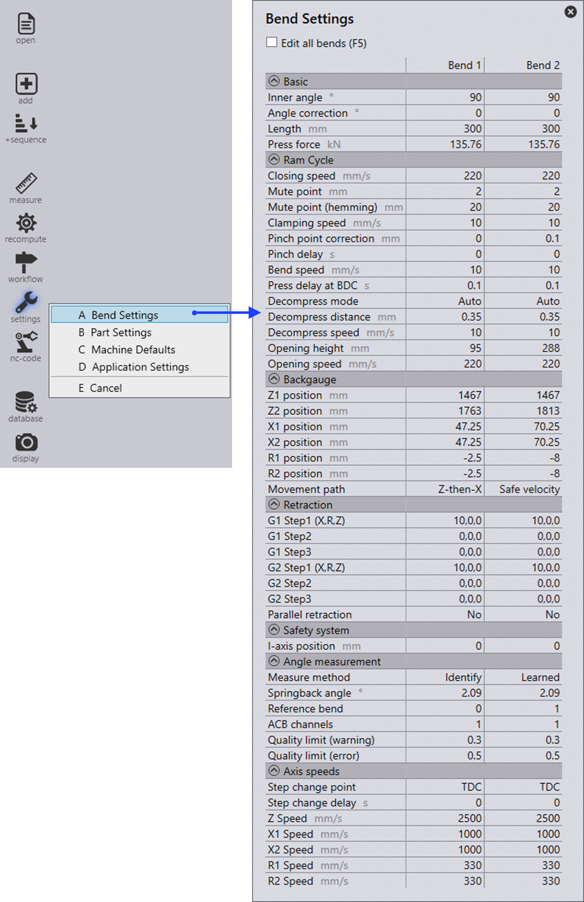
Once a sheet metal bend is tooled using workflow menu, select settings icon and click Bend Settings or shortcut key A.

Bend Settings
Table 1. Basic
Field Description

Opening angle

The opening angle is displayed here.

Length

The bend length is displayed here.

Press force

The calculated press force is displayed here.

Table 2. Ram Cycle
Field Description

Rapid down

The speed of the beam up to the mute point.

Mute point

At the mute point, the max speed ("Rapid down") is automatically switched over to the reduced speed ("Clamping"). The mute point is above the top edge of the lower tool. "Mute distance 1" programmed sheet thickness = distance between the tip of the upper tool and the upper edge of the lower tool.

Clamp

The speed of the beam between the mute point and the clamping point.

Clamping point correction

Adjust the value to compensate for variations in sheet thickness.

Waiting time at the clamping point

The delay is mostly required by automated machines. During the waiting time, the beam will stop at the clamping point. Adjust the value e.gif a robot’s gripper reaches around the part.

Press

The speed of the beam between the clamping point and the machine’s lower dead point (LDP).

Hold time at the LDP

The beam will remain at the lower dead point (LDP) during the hold time. Due to the hold time, the material has enough time available during the bend to deform. Increase the value e.g when air bending thicker sheets or when coining.

Auto-decompression

Activated (standard): Select the value determined empirically by TRUMPF for the decompression path.

Decompression path

With the decompression path, the tension in the machine’s frame is released in a controlled fashion after a bend, as it is under maximum tension at the lower dead point (LDP). The decompression path moves the beam upwards at a slow speed.

Decompression

Speed of the beam along the decompression path (decompression).

Opening

The beam opening is the measure by which the beam moves upward after a bending operation.

Positive value: Press beam is positioned above the mute point. Negative value: Press beam is positioned below the mute point.

Rapid up

Speed of the beam after the decompression path (decompression).

Withdrawal direction

Here you select in which direction the back gauge is to be withdrawn.

Withdrawal

Define withdrawal, value by which the gauge finger automatically moves away from the stop edge of the part once the part is clamped between the upper and lower tools (clamping point).

Table 3. Backgauge
Field Description

Z1 position (Finger 1)

Corresponds to the calculated position of the gauge finger Z1.

Z2 position (Finger 2)

Corresponds to the calculated position of the gauge finger Z2.

X1 position (Finger 1)

Corresponds to the calculated position of the gauge finger X1.

X2 position (Finger 2)

Corresponds to the calculated position of the gauge finger X2.

R1 position (Finger 1)

Corresponds to the calculated position of the gauge finger R1.

R2 position (Finger 2)

Corresponds to the calculated position of the gauge finger R2.

Table 4. Axis speeds

Z

Corresponds to backgauge Z1 and Z2 speed

X1 Speed

Corresponds to backgauge X1 speed.

X2 Speed

Corresponds to backgauge X2 speed.

R1 Speed

Corresponds to backgauge R1 speed.

R2 Speed

Corresponds to backgauge R2 speed.

Forms/Components Machine Defaults

      Copyright © 2023 by Metamation. All rights reserved.

    Compiled by Bento